| WBCF Transmitter
Site
This site was build in August and September
of 1998 by KK Broadcast Engineering and included a new 198 ft Rohn 25 tower
with Nott Ltd. Unipole, AGSC Ground System and a Nautel
ND1 1kw transmitter with associated feed lines.
This site became necessary when the City
of Florence began a huge ($52 million... with an M) expansion project on
an adjacent sewer treatment plant in the summer of 1997. The station
was not officially contacted about the upcoming sewer project until construction
had actually began. The City Engineers were a bit frustrated when
they learned that it would take approximately 6 months to get a construction
permit and that the station couldn't just be "loaded up and moved" like
they had planed. By the time a suitable site was located and construction
permit obtained (with plenty of associated FCC red tape) it was August
1998. By this time the stations old transmitter site was literally
an island. Construction had been on going over the previous year
and the only undisturbed dirt within hundreds of feet of the old tx site
was the area within the guy wires. The telephone line was cut at
least weekly, the power was knocked off several times and for days at the
time the tx site was inaccessible due to the construction.
Somewhere I have about 20 other images
of this TX build but they have come up AWOL. Sooner or later I will find
them and add them to this page
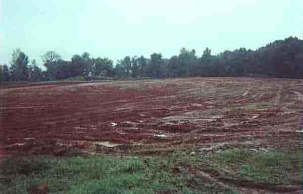
Site work just starting.
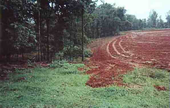
Just a few days before, this was a pond.
This area was filled about 15ft.
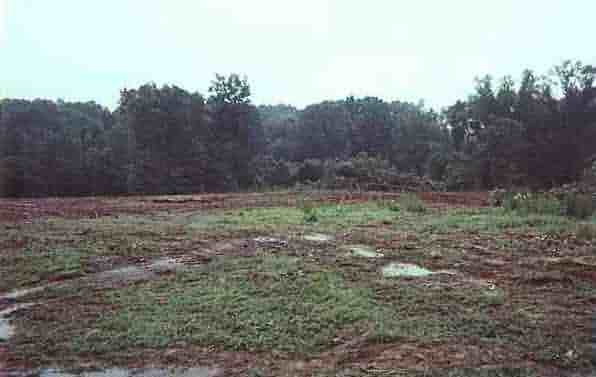
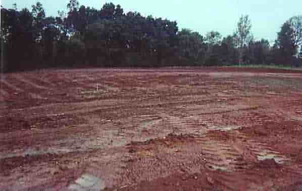
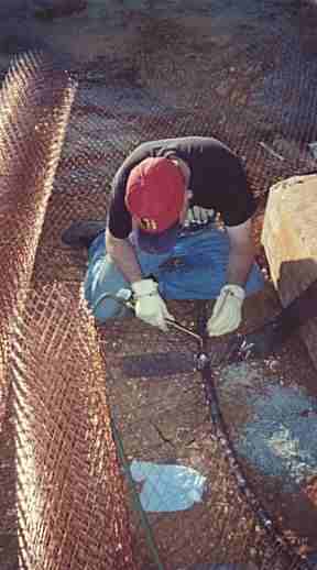
My #1 helperat the time, Shelton Barnett, brazes radials
to the common ground point. The ground screen can be seen on the
left side of this image.
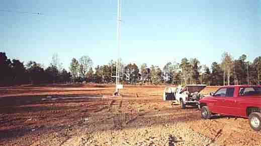
Looking north.
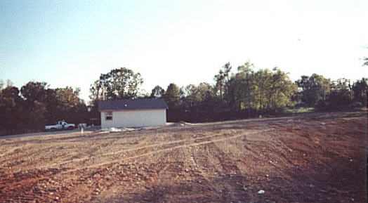
Looking south. The transmitter building
was built just off of the ground radials with coaxes ran under ground through
a large conduit that surfaces in a cable trough in the transmitter room
floor.
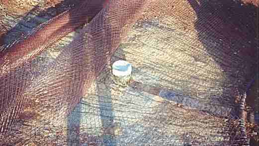
The white area in this image is a cover
over the well. The well was steel cased to over 100ft and is a total
of about 150 feet deep.
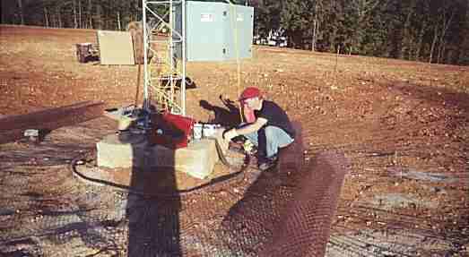
Looking northeast. Shelton still
working on radials. My rather substantial shadow soon causes him to believe
that there is an unscheduled eclipse and he runs home to huddle under a table with
his wife and child.
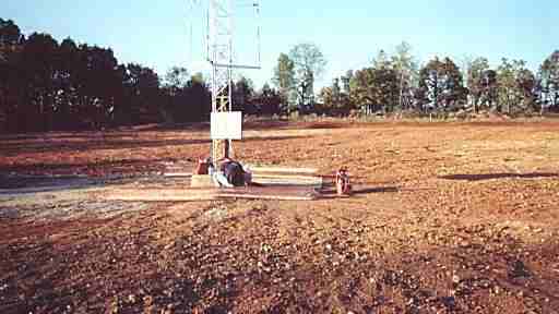
The bottom of the Unipole can be seen just
above the tuning unit.
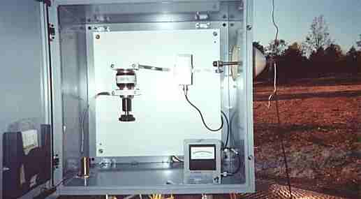
Internal view of the Nott Ltd. tuning unit.
Simple enough. The 7/8 coax enters the cabinet on the bottom left
side goes to the series vacuum cap, through a Delta sample
transformer and
on to the output insulator. The Delta RF amp meter can be seen in
the bottom right.
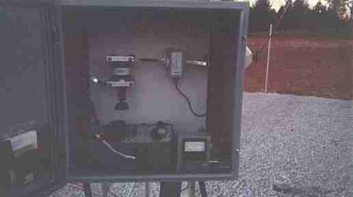
Another view of the tuning unit, with a
Delta OIB-3 sitting in the bottom. The gravel covering the ground
screen can be seen in the background. One of the fence posts for
the soon to be installed chain link fence can also be seen in the background.
|

